Thursday, 22 December 2011

I Got Wheels!

I've just got back from a couple of weeks away for work (firstly in the US and then in Cambodia)
I am exhausted.
But not so exhausted to investigate a large package that had arrived for me while I was away.

It was 7 weeks ago when I spotted a pair of Manurhin Scooter wheels for sale on the French website www.leboncoin.fr - this was about the time when I was realising that my own rear wheel was incorrect.  I contacted the seller and thereby started an epic story of email negotiations and logistics.
The seller - Morgan - was based near Lyon (mid France) and didn't speak English.  And I don't speak French but together we managed to communicate quite effectively via email and Google Translate.

Morgan wanted 80 euros for the pair of wheels.  Although I didn't really need another front wheel, his looked better than mine in the photos so I agreed at 80 for the pair.  He also had a pair of aluminum footrests for sale too, but at another 80 euros I had to decline.
Now I spend most of my life in front of a computer - I consider myself "always online".   Morgan, I suspect however probably isn't.  Replies could sometimes be a few (several?) days coming.  So it was with great delight when a few days later I received an email from Morgan offering me the footrests at a 'discount' price of 45 euros for the pair.  I gratefully took the offer and we started the (lengthy) process of working out how to 1) get the wheels and footrests from Lyon to Birmingham,  and 2) make the payment transaction

I had a quick look at courier prices from the likes of Fedex and DHL and these looked to be around £120-150 - this was going to be be an expensive pair of wheels!
And so I thought I'd try AnyVan, the online delivery auction site.  Within hours of posting my need, I had my first offer to collect and deliver - £300.  Over the next few days various couriers bid down the price to a far more sensible sub-£100.
In the meantime, I was trying to pay Morgan.  I was keen to pay at least a deposit in order to secure the sale.  Morgan doesn't use PayPal but would accept a cheque or maybe a bank transfer.  We spent a good couple of weeks trying to find a mutually acceptable payment method, and at one stage when emails were particularly slow in coming I thought that maybe it was all off, he'd either sold them elsewhere or had simply got fed up with the hassle of it all.
In the meantime, back to the courier;  Offers were down to £60 and I was ready to accept, but had to apologise to the bidders that I couldn't commit as I hadn't actually bought the items yet... in fact I didn't even know if they still existed for me.
It was driver 'swift1' (mark) who first suggested that he could do a pay on collection for me if it would help facilitate the process.  Unfortunately Mark couldn't make the time window that I needed (but I should say now that Mark was a superstar in doing his best to try and make this work - and if I could I would give him 100% feedback based on his efforts alone), and so eventually I found 'philbfc' (Phil) who was equally enthused to do his utmost to help me.

Eventually Morgan responded to my email;
"Sorry i didn't have time to give you answers. There's no problem for manurhin wheels they are for you"
I was mightily relieved and followed with a flurry of activity to arrange money and dates (doubly complicated by the fact that I wasn't going to be around to pay on receipt when the wheels were eventually delivered to my house)

Between Phil and Morgan (while I was in Atlanta), they arranged a pay-on-collection at 11pm on Thursday evening as Phil was traveling through Lyon on his way back to the UK
That night I received the following email.  It warmed my heart;


Bonjour 
Le colis est partie hier soir .
Le règlement a bien été effectuer .

Je suis également contant que les pièces soit pour une personne passionner .
Je compte sur vous pour redonner vie a ces Pieces et les remettre en belle état . 

Hésitez pas pour m envoyé des photos de votre projet .

J espère que le colis arrivera bientôt chez vous.
Amicalement 
Morgan


Saturday just gone (while I was in Cambodia) Phil dropped the package off at my house, and today within 15 minutes of returning from a grueling 21 hours traveling halfway round the World, I actually touched the wheels that I had first inquired to buy 7 weeks ago.
I was delighted :-)
They might not be the colour I need for my bike, but I reckon they are in such good condition that I wont have to do anything to the wheels, tubes, tyres or hubs to get my scooter up and running.
What a great christmas present (to myself ;-)

Friday, 9 December 2011

Painted frame

Its been a while since i posted any updates on my blog.  This is partly because I've been so busy with work I haven't really had much time to get my teeth into any proper jobs on the bike.  I have managed to grab a moment here and there to work on bits and pieces but until I have completed something it seems a little pointless to be writing about it.

However, in order to keep something rolling along, I did take my frame, front forks, rear swinging arm and a few ancillaries in for painting a few weeks ago.  I was concerned that I might be being a little premature with this, but as the frame really didn't need much re-work, I thought getting it painted would at least be progress of some sort (and could be happening without my involvement while I was busy elsewhere)

I decided that I would get the scooter powder-coated (rather than wet-sprayed) as I am lead to believe that Manurhin scooters were indeed one of the earliest adopters of electrostatic powder-coating for motorcycles.  As I had already used (and was very pleased with) Redditch Shotblasting for my powder coating when I was rebuilding my Vespa it was natural that I would go back to them.  I phoned them up and arranged to drop the parts into them the following day.  When I arrived at their unit in Redditch, Dave came out to meet me "Oh its you" he said, sounding a little miffed "I didn't realise it was you when we were talking on the phone"
I was a little taken aback by his reaction to seeing me, and I asked what he meant.
It turns out that Dave had read my blog about the Vespa rebuild and was a little concerned about the 'bad' press I had given him.
Well, my first thought was "Wow, someone actually reads my blog?!" but then I quickly panicked wondering what on earth I could have said that was bad.  Not only do I try to avoid writing 'bad' things about people, but I thought I had expressed my delight with their work.  I don't need to explain my writing here - but to cut a long story short, He was gutted because he thought I'd written a bad review about his company, and I was gutted because he had interpreted my writing as a bad review when actually it wasn't.  Anyway, I think we are friends again and for the record I think Redditch Shotblasting do a marvelous job and I thoroughly recommend them (just remember that all good thing come to those who wait.  I waited patiently this time for the job to be done (3.5 weeks) and once again, I was delighted with the end result)

I had initially decided that the frame should be black - I think all chassis' should be gloss black - but talking it through with Dave and looking at his very extensive range of colours, I changed my mind at the last moment and decided to have it coloured as near as damn it to the original colour of the bike - Maroon.  I say original because as I have already discussed on this blog, I'm not 100% sure what the 'original' colour actually was.
As much as I like a black chassis, I am very pleased that I chose the Maroon in the end - it looks fabulous

Frustratingly - exactly the same as when I picked up the painted Vespa frame - I have to leave the Manurhin frame wrapped in its bubble wrap for a couple of weeks now while I jet off for work.
But at least I have something exciting to be getting on with over the Christmas holidays :-)

By the way - Did I mention that I think Redditch Shot-blasting and Powder-coating do a great job ;-)

Tuesday, 15 November 2011

Refocusing

I had been feeling a little down recently over this project;  Everything was broken and everything was costing me money.  But I love being in my garage and I rather like the bike, so I couldn't bring myself to simply walk away from it.
It dawned on me that the bottom line was simply a TIME and MONEY problem.  I was investing a lot of time in fixing things, and investing a lot of money in procuring things that I couldn't fix.  And I felt that I could barely afford either.  I was fairly happy to spend my spare moments fixing and repairing things, but I was beating myself up over the increasing costs and this was getting me down.

The other day, while resting against my bench and feeling a little weighed down by all the problems still to be overcome in this project, I started to wonder what would happen if I could let go of some of the constraints that I seem to have subconsciously imposed upon myself.  As I thought about it, there appeared to be a number of them;

  1. I must finish any project that I start.  Anything else will be a failure on my part
  2. I must get this scooter ready to ride to France next summer
  3. I am obliged to 'restore' this scooter back to its original design and former glory
  4. I must not spend more money on the project than I can expect to get back should I sell the bike
In the grand scheme of things this is not a terribly difficult project, and there is no reason why I couldn't get it finished in order to ride to France next summer - this is quite a motivating vision for me.  However to achieve this, I suddenly realised that perhaps I have to stop (within reason) worrying about the cost - If I need bits, and someone has them for sale, perhaps I should stop fannying around and just buy them and press on with getting the job done.
It had an amazing effect on me; with this sudden clarity I really felt a weight come off my shoulders.
And I thought on.  There is no way this scooter will ever be considered as "restored" to its original design, but there is no reason why it cant be 'good enough' as a resurrection from a barn-find grave.

And so with this new view on the project and being much more conscious of my self-imposed constraints, I feel once again motivated.  I WILL finish this project and it WILL be 'good enough' to ride to France next summer  :-)

Monday, 31 October 2011

Seats

Seats?!  I am a long way off needing seats for this bike.  But I did need to remove them in order to investigate the state of the body/cowl (which surprisingly isn't too bad!)

I don't need to say much about the seats - the pictures say it all.   Everything needs repairing


3 points of interest;
1.  Who was the idiot who thought that 2 copper plumbing brackets would suffice as a repair for the front seat hinge?  And how did the original steel hinge get broken in the first place?
2.  What is that reference plate screwed to the underside of the drivers seat?  Is this a Manurhin reference? I don't think so, but it looks like its been placed there with purpose.
3.  Those foam cushions look to be original..... but have they been in a fire?  they look/feel/smell charred.

 Oh how I wish inanimate objects could talk

Wobble of confidence

I felt really low about this project over the weekend.  This really is a hopeless case.  Every part of the bike is buggered, and it really isn't worth the effort to try and fix - it certainly isn't worth the financial cost.

I enjoyed working on the engine.  That seemed like a worthy challenge - to try and bring the heart of a machine back to life.  And once I had it up and running I was rather keen to see if I could put it into the frame and fix up some wheels and see it I could get it moving.
I managed to control my disappointment last week when I realised that my rear wheel was not original and needed replacing, and I pressed on with preparing other parts.  However, there are only so many knock-backs a man can take

I had turned my attention to the front wheel and stripped the hub and brake assembly (which to this point I hadn't looked at closely) and as I removed the Huret speedo worm drive and found it to be smashed, my heart sunk and for the first time I questioned whether it was all worth while.  There must be a point where a smart man would cut his losses and move on to more valuable things to do with his time and energy.

I didn't know wether to laugh or cry.
I walked away from it all for a while and went and did some gardening chores..... but eventually (inevitably?) I was drawn back to the garage.
Deep breath.
Press on.


I'm still not really sure about this project.  I am fast exceeding my budget, and if I am going to have to replace every little part that some bodger in the past has fucked up then I will simply grind to a financial halt.  I love tinkering in the garage, and so for this reason I shall continue to do what I can - but whatever I do, this project is certainly not a "restoration" - at most it will only ever a "resuscitation" - anything else simply isn't worth it.

Steering Lock

steering lock - removing cross pin and clip
The Manurhin has a lock on the steering column - not for an ignition as might first appear (there is no ignition security key on a Manurhin) - its a steering lock.  Allegedly there should also be a lock on the drivers seat to restrict access to the petrol tank - but I don't appear to have one of these.

Obviously, my scooter doesn't have a key for the steering lock.  But fortunately the lock is not in the engaged position so the steering turns freely.
As I have been preparing the frame for powder-coating, getting the lock mechanism out seemed sensible even though I could probably get away with simply masking it off and leaving it in place.  Trouble is, its a real bugger to get out without a key.  I should have just left it, but it started to niggle me and I felt driven to investigate (especially as I wasn't prepared to spend what one locksmith quoted me to get it removed and fitted with a new key... £130!).  Over the period of several days I kept returning to this little puzzle wondering what on earth could be keeping it from sliding out.

Fellow Manurhin owner Roy had already told me about his own experience with removing his steering lock which resulted in drilling it out.  I was keen to avoid such destruction but was grateful to learn however that the lock is German-made by Neiman.  You can buy Neiman locks on eBay (though I cant find one to my exact dimensions) so I did a google search for "How to remove a Neiman lock", and turned up a couple of forums discussing this very problem (it seems I'm not the only person to have bought an old motorcycle with no keys)  Sadly though these discussions don't answer the problem completely so I was still in the dark as to how it operated.

marking where the restriction is.
Note there is no external pin or fitting here
The lock is very small; a mere 12mm diameter brass barrel and bolt, and it simply slides in a steel tube welded to the headstock of the scooter frame.  After removing a spring clip and a cross pin, I could slide the lock assembly laterally back and forth within the tube by about 6mm, but there was a dead stop that was preventing the barrel from removing fully.  Investigating with magnifying glass and mirrors down the headstock provided no clue as to what might hold the barrel in place - there was no obvious retention or lip.

To prove its free movement to myself I cut a long 3mm wide strip of Guinness beer can and carefully slid it between the brass barrel and the steel retaining tube.  I was able to push this thin strip all the way along the tube until I could see it pop out in the headstock tube - there was nothing in its way.  Withdrawing the strip, and repeating the process around the complete circumference of the lock barrel I was to discover that there was one place where (at about 1 O'clock) where the strip hit a restriction.


drilled out outer tube, and internal pin
The thing that puzzled me was that I could find no external evidence of a retaining pin and as the steel outer tube was no more than maybe 2mm thick, there surely wasn't going to be a stepped ridge.  However, I was now very intrigued, and as much as I didn't want to do anything destructive, I decided to drill a 5mm dia hole into the tube at the place where I had deduced the restriction to be.

Sure enough, drilling a hole in the external tube at this point revealed a pin in the brass barrel that once removed (drilled with a 2mm drill) allowed the barrel to slide easily out of the outer tube.

Once out, all became clear.
This is an incredibly simple design.  Simple but ingenious.
Once again, my assumptions about the engineering principles let me down; I had assumed that the outer tube was 1. simply a carrier or support for the lock mechanism - I would never have guessed that it was actually part of the lock mechanism, and 2. it was too small and skinny a piece of tube to have any integral machining done to it.

note the 2 grooves machined inside
A closer inspection inside this steel tube reveals that the inside wall has two machined grooves in it (remembering that this tube is 12mm ID with 2mm thick wall - this is an intricate bit of machining) and it is these grooves that the pin in the brass barrel/bolt engages with.
[apologies for the poor quality of photo - taken through a magnifying glass with flash - but hopefully you get the idea]

So I had settled my curiosity, and I can now send the frame off for powder-coating without fear of damaging the lock....... what a shame I damaged it by removing it :-(
I dont think I have done anything irreparable to the frame - though I am reluctant to weld that drill hole up now as this would certainly ruin the internal grooves.  Even with this hole, If I find a replacement barrel/bolt, it should still operate properly.

perhaps this hole can simply become a jolly big greasing point.


Just in case anyone is ever after a replacement steering lock.....


Thursday, 27 October 2011

Paint colour

I am sure that thinking about paint colours at this stage of this project is a bit like trying to choose the name of your rock-band before you have your first rehearsal (How many times have I done that in my youth?! :-)

However, while I've been working on the chassis I have become curious about the paint colour.
According to documentation, the Manurhin Scooter was technologically advanced for its time, and not least for its production paint.
According (I know this is a tenuous link of accordings) to wikipedia; "According to Bonhams the MR 75 “was constructed to a high standard and must have been one of the first motorcycles to be painted electrostatically, a process commonly known as ‘powder coating’.


I've used powder-coating many times,  most recently on my Vespa PX, and in my experience its very hard wearing and provides a nice thick even coat without need for priming and undercoating (as is necessary in conventional wet cellulose spraying)  And its for this reason that I've started to become suspicious of what paint is on my scooter and therefore what the original colour might have been


Up until now I have unquestionably believed that the colour of my bike was "Maroon" - I understood this to be a standard production colour.  A 'Motor Cycling with Scooter Weekly" magazine review of the "Manurhin 'Hobby de Luxe'"in December 1959 states;
"Colours available; Choice of red or Blue for de Luxe model;  Green only for standard model"


I had assumed that my 'Maroon' was the same thing as their 'Red', but I have certainly seen more pillar-box red examples of Manurhins, so I may be mistaken in my assumption.
I think I would be right in saying that in general, pale blue and pale green are certainly original colours, but there are a good number of examples of red, maroon and pale yellow Manurhins out there.  This is not the first example of model confusion that I've talked about in the Manurhin/DKW scooters, I'm starting to get used to the ambiguity now.


flaking paint on mudguard suggest a respray
But back to my scooter;  the paint on the chassis (and body) is maroon, but is has an undercoat of what I was seeing as pale yellow.  Maybe early powder-coating techniques required a 'primer' of sorts?  Or has my bike been repainted at some stage?  The external body has certainly had some respray work - this is evident in flakey paint in places - but never the less, this respray has tried to be faithful to a colour underneath.
The thing that troubles me is that if my chassis has been repainted then whoever did it, did a bloody good job because the maroon paint over the yellow has got into every nook and cranny of every component (would you really be bothered to paint the underside of the rubber suspension cups?) - its as if the maroon colour has been put on by dipping, or electrostatically painting.  Has it been repainted or is the maroon-over-yellow a production process?


what is this colour under the maroon?
what is the colour? and what is it doing here?


So, I investigated further by literally scratching away at the surface.  When I expose a large patch of the yellow under-colour and compare this to a pure white, I cant help but ask myself - is this yellow actually a pale green?  Was my bike originally the beautiful pale green of the 'standard model' - check out the pictures of these two bikes in what I am assuming to be true reproductions of original colours 


I'm rather confused about the whole thing.  However, I have decided that I am certainly going to have the chassis and associated under-body components powder-coated in gloss black (in my opinion, chassis' should always be black.  And black is cheaper to have powder coated than colour)
As for the body colour..... I have plenty of time to think this through :-)


Wednesday, 26 October 2011

Rear wheel

Crikey, will the problems ever stop?  I shouldn't be surprised really, nothing is ever straight forward on this scooter.
I've had a niggling suspicion for a while that my rear wheel was not as it should be, and now that I am starting to work on the chassis,  I will be needing wheels shortly to stand it on.  So I dug the wheels out of the shed.


Right from the beginning, I couldn't understand why the brake lever was on the opposite side of the hub to the chain sprocket - drawings showed them both on the same side of the wheel.

Now that I look more closely at my wheel, I see that it is totally different to what was designed (according to the parts manual)


In addition, I notice that the designed chain sprocket (they call this the 'chain crown' in the parts manual) has 56 teeth - my wheel has 32 teeth.  Cripes! with a ratio like that my scooter must have run like a rocket!  Perhaps my scooter had been make into a special racer?

The more I look at it, the more I think this is not the original wheel.  I wonder what it came off? and why would anyone change it anyway?


At one stage I thought I might try and work with it (and fit a larger sprocket) but on closer inspection, I see its actually rusted through at the rim - I don't mind trying a bit of tricky welding, but I don't fancy risking a wheel failure, and so it looks as if I am in the market for a replacement rear wheel :-(


Now as chance would have it, I do happen to have a spare rear wheel hub and set of spokes (I bought these ages ago in a bundle of parts from a chap in France)  So if push comes to shove, I could try and re-spoke a new rim..... but I'd still be in need of sprocket and brake assembly.

So I guess its fingers crossed now to find a complete rear wheel assembly.

Sunday, 16 October 2011

Beltomatic safety switch logic

I think I've assembled, fitted and wired up the safety switch correctly.  And I can see the logic in how this switch works, but I don't think my logic matches with the logic of the owners manual.

My logic;
At rest, set the switch lever to touch the pulley so that the switch is open.
As the engine speeds up, the pulley moves away from the switch lever, and in doing so, the microswitch 'makes' (grounds to earth) effectively stopping the engine and letting the pulley slow down and come back out again to the switch, 'breaking' the earth and allowing the engine to start again


Owner manual logic;
At rest there should be a 3mm gap between the switch lever and pulley.  That means the switch is 'made' (earthed).  As the pulley speeds up so it draws away from the switch lever - in this way, as the pulley only ever pulls away from the switch lever, it never actually touches the switch??!!

For a detailed 'official' description (I assume its official, but I dont know where it was published) of how this switch is designed to work take a look at this document on the Manurhin Scooter Interest Group website.  My interpretation of what I read is exactly as I describe in my logic above.... but I just cant see how the switch works in their setup.

The bottom line is that I think the switch lever should be touching the pulley when at rest.  The guide wants a 3mm gap.  What am I not understanding?

I am sure that I have got something wrong - I dont doubt that, and I look forward to someone making it all clear for me

Starting the engine

I went to a scooter fair this morning in the hope that I might find that elusive bit of ducting that goes over the cylinder head.  It was a wasted trip.  Although the event was massive, it was a complete "Lambrespa" fest.  Other than a completely knackered Zundapp Bella, there was not an unusual scooter bit to be seen.
So I dashed home determined to take one more step toward bringing a rare machine back to the world.

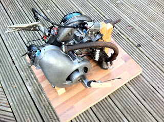
Now my engine is all mounted up on a test bench, it seemed only sensible to see if I could start her.  I cobbled up a little fuel reservoir, and gave it a yank.
Doh!  I yanked too hard and promptly yanked the starter rope right out.  Boy, was I mad with myself.  I obviously hadn't swaged the end-cap on the wire tight enough.  Grrr, It wasn't a difficult job to do first time round, but it was a pain in the ass this time round as I would rather have been trying to start the engine.

Finally I was ready.  Would it run?
Would it run!?  First bloody pull!!  :-)))


She stalled a couple of times, but restarted ok.  There was heaps of white smoke (but I had purposely made an oil rich mix).  Eventually however it refused to start.  The carb was flooded and the cylinder soaking in fuel - I'm guessing the carb float is sticking, but who cares right now? She starts!  And that is quite amazing when you consider its been made up of a load of different parts that have never worked together before.
I wonder when the last time was that this engine ran? its got to be at least 30 years ago.  I am so amazed (and quietly delighted ;-)

Bench testing the engine

I've rigged the engine up on a solid base so that I can start it without having to mount it in the frame.
And I've replicated the electrical circuit so that I could see if the power unit as a whole did what it was supposed to


So does it turn over alright?  Yes it does! sweet and smooth :-)
Have I got a spark?  Yes I do!  looks bright and blue :-)
Does it run?  Don't know yet, but feeling confident :-)

Sorting out the ignition

This blimin' ignition is trying me.  I seem to have heaps of information on all the variations of manurhin electrics, and yet so little on what my own should look like (all electrical wires and components had been stripped off my bike before I bought it)

After comparing schematics, reading various magazine articles (kindly sought out for me by fellow Manurhin owners) and deducing what I could of the windings on my magneto stator, I eventually came to the conclusion that my bike was designed to have an ignition coil.  With the help of a fellow Manurhin owner, we found a French supplier of ignition coils as designed for the Manurhin, but after a few further enquiries, it appears that any old single cylinder 12v coil would do the job, so I popped over to Vale Onslow to buy one.  While there I asked them about condensors and stator windings - I'd read a lot about them on forums, but I was keen to hear what the experts thought.  After lots of sucking-through-teeth and general mockery for it not being off a proper motorbike, the general expert opinion was "just try it and see if it works"

So armed with a new 12v coil I set off home to "just try it".  The circuit is pretty simple so there's not much to experiment with or get wrong.... so why did everything seem to be shorting to earth?

I come from the school of "if it aint broke, dont fix it", and so to this point I hadn't bothered to do anything with the breaker points other than clean the contacts - How foolish can I be?  You'd have thought by now that I'd have learnt my lesson;  Everything on this scooter is broken!
It wasn't until I had completely stripped the points down to the tiddliest of fiddly bit that I discovered that someone else at sometime in the past (presumably just after the last time it had run) had also stripped the points.... but reassembled them incorrectly.  By simply getting a steel washer and an insulating washer in the wrong order, the whole unit was earthed and rendered useless.

Setting the points is dead easy - although the owners handbook does give a gap size (.016-.02 in) they helpfully also suggest "the thickness of a postcard" - so thats what I set them to.
More tricky was trying to work out where best to position the advance/retard - I reckoned a good guess would be 'in the middle'

so many 'little' things to do

I've started to lose track of the order of things.  I seem to have so many loose ends on the go at the moment.
I've been trying to get a few evenings of garage time in to try and make progress with this engine.  I'd like to see if I can get it to run (I think that would give me a good boost to working on the frame and running mechanics)
There seems to have been lots of little time consuming (but not particularly interesting) jobs to be done.  For example;

cleaning the carb air-filter
- fitting the wire rope to the pull start assembly.  The manuals show a special tool for holding the recoil spring while fitting the rope.  I'm not so sure its essential - I managed it ok.

and,
- repairing the perished carburetor rubber air-in pipe (which interestingly draws the fresh air in via the engine case - presumably to warn the air in advance)  I used a gel super-glue in all the cracks - it seems to hold

Wednesday, 12 October 2011

New starter sprocket

The starter engage-sprocket was heavily damaged on the engine that I bought.  It was severely knocked out of line and had badly chipped teeth (someone suggested it looked like an idiot might have tried to free a seized cylinder by whacking it with a hammer and cold-chisel (another reason I was keen to get the crank-shaft balanced)
And so I was committed to repairing or remaking a new sprocket.

For some reason the sprocket on the flywheel was in two parts (were they designed as pressed pieces 'laminated' together?).  I decided to make my new one in one piece - 7.5mm thick steel plate.


A couple of hours sawing and filing and I was ready to go.  However I was a little concerned about the new sprocket wearing faster than it should, so I decided to case harden it.


There are plenty of tutorials on case hardening on the web ( here is a nice simple explanation of how it works) However I chose this one because I had some charcoal.  It was all a bit school-boy experimentation with oxy-acetylene and steam and stuff, but I enjoyed the process.  Whatever the outcome of the metallurgy exercise, the best way to ensure it doesnt get too much wear is clearly to build the bike up to be an easy starter.... but thats a whole different problem

The original sprockets were riveted in place.  I chose to use M4 stainless steel button head socket screws, with a good dob of lock-tight to ensure they don't come out accidently

Tuesday, 11 October 2011

Nuts and Bolts

I started writing this blog to keep my dad up to date with my Manurhin project.  As time has gone on, I've found a small group of people who appear to enjoy reading about the trials and tribulations of trying to bring this sorry machine back to life.
Some of these people are restoring their own Manurhin scooters and for them, I like to make reference to the documents I've used, the problems I've solved and the suppliers I've found.

Recently I had need to buy some special screws, and really struggled to find an engineering nuts & bolts stockist with a trade counter.  Where have these centers of engineering communities gone?  Where are the knowledgeable old gentlemen in their brown cow-gowns who could find just the right bolt for any problem you might put on their counter?
After a little searching, I managed to find 2 such businesses who when I phoned said no, they wouldn't mind if I arrived asking for 3 bolts.  One incidentally was run by a lady..... from her house! - There's the modern engineering world for you!

The other company was run by a single chap from a tatty old industrial unit hidden among several huge car-breaking yards.  As he was searching for the parts I wanted, we chatted about his business and the way it was changing; going one of two ways.  Nuts & bolt suppliers were either bagging bolts and selling them for pennies on eBay, or they were servicing the specials market (He held up an impressive £40 nut, the size of a grapefruit for the MoD).  Then he asked me what my 3 bolts were for and I told him about the Manurhin and how I liked to write on my blog about the interesting and helpful people I have met while solving the many problems I encounter.
"Let me stop you there" he said
"Don't tell anyone about my place"
I thought he might be concerned about his MoD customer.
"I don't want any more people turning up here asking for 3 bolts here and 2 nuts there.  Its just not worth my while."
I paid him my 2 quid and left.

Ignition coils

Why cant I find any information on which variant of Manurhin had an ignition coil, and which didn't?

Close inspection of a French language 'Guide-Reparations' (repair guide) shows an electrical circuit (without the beltomatic integral safety switch) and lists out all sorts of useful information about strokes and bulb wattages and chain links etc etc.... and right down the bottom in the corner, almost as an after-thought, they say;

"Fitted with a Regulator.
A wire (green) connects to the handlebar switch on the left.  The other wire (purple) connects to the regulator contact.
Note; Certain vehicles are equipped with an external ignition coil"

Oh, come on Manurhin! get it together!  you cant simply dismiss the safety switch and HT coil just like that! Where are the details??

Frustrated, it is starting to dawn on me that my engine still isn't complete.  As I began to calm down I went in search of more information


The french for "ignition coil" is "bobine d'allumage" and a quick google search bought up someone selling a Morel primary ignition coil for the Manurhin for 70 euros, but no specific details of an appropriate coil for my scooter.

Although I dont think it helps me immediately with the sourcing of a coil, I thought this Manurhin specific conversation about ignition systems might be a useful read in the near future.  Its a great example of a small bunch of enthusiasts working together to solve a technical problem.  I was especially delighted to read toward the end of the discussion an expression that only a French scooter rider would have the balls and style to say;
"Une fois de plus la ruse et l'intelligence ont triomphé de la force et de la bêtise!!!"

Monday, 10 October 2011

Repairing the exhaust manifold

The more I work on this scooter, the more I think I must be mad.  The whole thing is in such a state, its hardly worth the effort.  Its certainly not worth the financial investment - I have already spent £640 and I am nowhere near getting this thing running, let alone road legal.

Every bit of this bike appears to be either missing or damaged (I really would love to know the history of it all)
Take the engine for example; Although the eBay advert said "Looks like its all there" My engine was missing a carburetor, a pull-starter assembly, an air-duct and a beltomatic Integral safety switch [and remember, this is just the engine - elsewhere, there is no electrics, electrical switches, lights, or brake cables.  In addition I am also missing all of the pleasantries like badges, footrests and useable seats - the whole thing is in a very sorry state]

However, being the 'glass-half-full' (or should that be 'plain stupid'?) sort of chap that I am, I've been pressing on and collecting the missing bits here and there, and kidding myself that I could actually resuscitate this poor old scooter.

But thats enough about the 'Missing' parts, what about the 'Damaged' parts?
The cylinder barrel is just one example.  The exhaust manifold has had its bolt hole smashed off.  In the early days of this project I was of the mind to get it into a specialist welder to build up the iron casting and machine back to shape again, but as costs have started to escalate, I decided to look for a solution that I could do myself.

Its not elegant, but I think its adequate and man enough to do the job of holding the exhaust tight to the engine.  A simple threaded plate held in place by a strap around the manifold.
And its a darn sight cheaper solution than buying a new barrel - There is someone currently selling a barrel/head/piston set on German eBay for £128

Beltomatic belts

The drive belt on the scooter as I received it was rock-hard with age and was certainly in need of changing.  I couldn't find any reference numbers on my belt but fortunately there seemed to be lots of online references to Manurhin drive belts (though the more I looked, the more I noticed that reference numbers do vary everso slightly)
There also seemed to be talk about how difficult it was to find these replacement belts, though I have seen one come up now and then on eBay and Leboncoin.fr

I decided that the specification number I would work to was 22x8x575Li

I needed to get some new oil seals for my crank bearings, and so while asking my local bearing stockist (IBS Bearings Ltd 0121 558 4141) about those, I also took the opportunity to ask them about drive belts - They immediately recognised the spec and quoted me £37.50
I was rather pleased with myself that I should be able to find a belt as easily as that.  However it wasn't until later that day that a fellow Manurhin owner told me that he had just been quoted £12.50 for exactly the same thing! - well, actually its not exactly the same - 22x8x565 - but does this make a difference??
Only time will tell

Wednesday, 5 October 2011

Finding the right electrical schematics

You've got to have your wits about you in this game.  There is a lot of documentation about the Manurhin (for which I am very grateful) but I cant afford to make assumptions that I might have read it all carefully.

As much as I might try, I still haven't got my head completely round all the variants of DKW Hobby and Manurhin Scooter models and variants.  I get the sense that it was all a bit of a free-for-all at the Manurhin Scooter factory with everybody trying a little modification here and a redesign there, and in doing so the technical authors must have had a hell of a job trying to keep up with creating appropriate handbooks.

One example of a variant is the HT coil.  Some scooters have them, some don't.  Mine doesn't, but does that mean my scooter has a particular model number?

Wiring schematic for bike with mechanical 'clutch'
Another example - and the one thats been bugging me is the Beltomatic "electric safety device" clutch control.  Its ingenious no doubt, but there doesn't seem to be any rhyme nor reason as to what bikes had this style of clutch while others had the manually operated lever clutch device.
Note; I may have my facts all of a muddle here - I hold my hand up to that - but I will investigate further and try to create a time line of how and when models and variants came about.  However, just as an example of how messy all the terms are, I read the following in one brochure;

"Manurhin - The only scooter in The World with completely automatic transmission (Uher Beltomatic system) known as the "Variator"

My own scooter has the 'electric safety device' style of 'clutch' - which some brochures refer to as "Beltomatic Integral" - as introduced at the 1957-58 Motor show.
Although the original switch part was snapped off my engine when I bought it - I have since managed to buy a replacement, and as I get closer to wanting to start my engine I began to wonder about how this electrical switch is wired into the running circuit of the bike.... and this is where my assumptions have made a bit of a fool of me.

Wiring schematic for bike with 'electrical safety' clutch
I had been reading the Manurhin Scooter owners manual with great interest, but frustratingly couldn't find any reference to the 'electric safety device'.  The manual only talks about the mechanical lever type.
It never occurred to me that Manurhin in their wisdom might have produce exactly the same Manurhin Scooter owners manual BUT with just a couple of pages differing to cover this clutch difference..... there's not even a little reference number or identification on the alternative booklet to help a dealer know which manual is which.  Its a modern-day data-management nightmare!

It was only after plenty of scouring through the many different copies of manuals that I have (gratefully received from various other Manurhin owners) that I suddenly noticed - with great delight and relief - the differences in publications. [I hope I have made this clear now in the reproducing of the two different owner manuals on the Manurhin Scooter Interest Group website]

So I now have a wiring schematic for how the 'electrical safety switch' clutch control is wired in.  And it looks to me to be a simple case of grounding the LT to intermittently stall the engine and prevent it from revving too hard and thus engaging the belt drive.

spark plugs

I cant for the life of me find any reference to the specification of the correct spark plug for my scooter.  Various owner manuals can tell me that my ignition is "Magneto, fixed spark advance" and that my points should be ".016" - .02" " etc but no mention of what sort of replacement spark plug.
My Manurhin came with a spark plug in it, but as the bike in general had been so abused, I am being cautious as to wether this is a spark plug as specified.

The plug in my bike is an AC 44-5V

I came across The Green Spark Plug Company on the internet and thought I would do a little research into sparkplugs.  Crikey! I hadn't realised how complex it all was, and so I gave them a call to see if they could enlighten me.
The very helpful chap at GSPC informed me that an AC 44-5V was very likely the correct plug for my scooter (and very common for scooters in general).  They were out of stock of those but the very reasonable J8C would be a suitable alternative (see the photo alongside for a comparison of these plugs - seems like a 'copper core' electrode is the only difference - and these are supposed to be better for high temperatures..... not that i imagine my Manurhin getting that much wear)
I pressed him further for suggestions on plug caps, and once again he informed me that my application was pretty common and a standard non-suppressed LZFH would do the job handsomely.
Feeling flush I took the plunge and ordered a meter of 7mm PVC HT lead too.

Total cost including postage; £7.82

Tuesday, 4 October 2011

Starter rope

The puller rope on my starter assembly is damaged.  It was damaged when I bought the starter assembly off eBay, and until now it hasn't been a problem for me to think about, but as the engine slowly comes back together, I need to get it working again.
Stripping the spring return assembly is all pretty straight forward, but it clearly is something that hadn't been done for a while - it was full of a thick cake of mud, dirt and oil, severely restricting the free movement of the engagement plates.

I had originally intended to simply replace the original and damaged wire pull rope with a modern nylon rope designed for lawn mower engines, however it turns out that a lawn mower pull rope is too thick to fit comfortably around the assembly, and so I had to go in search of a replacement flexible wire rope.

There are many specifications for wire rope, and not all wire rope is suitable for such regular wrapping and unwrapping around a tight diameter like the Manurhin starter device.  And so it was with little confidence that I went to see a local wire rope supplier.  But how wrong could I be?

Rope Services Direct Ltd were fantastic.  Mike was not only interested in my problem, but had exactly the wire rope i needed (2.5mm dia. Multi-strand, stainless steel) and hundreds of other types of wire besides.  He also threw in a handful of appropriate end terminals for me - all for the price of a beer!
Incidentally; Rope Services Direct Ltd can also create bowden cables to any design and end fitting, so they may well be very useful a little further down the line when it comes to break and throttle cables too

Monday, 3 October 2011

Registering my scooter

I've had a little niggle in the back of my mind for a while now, and although it is still a long way off, I am slightly concerned about the process of registering my scooter - especially as I have no previous documentation or proof of its originality [though I hope in some way this blog will be able to illustrate its authenticity]
As I was eating my breakfast the other morning I was reading the latest edition of Old Bike Mart (I thoroughly recommend everyone subscribing - its better than.... well anything that you think is really good)
I read with interest about a 1928 Indian scout project that had just been "issued a dating certificate" so that the owner could apply for a period registration number.  This piqued my interest and so I dropped the writer an email to ask more about this process.

Mike Worthing emailed me back;
"My dating certs are accepted by DVLA. I provide the cert, all the DVLA paperwork filled in for you to sign and retain, and a step by step drill to follow to obtain an age related number. The fee for this services is thirty pounds (payable to me please) and my address is in Old Bike Mart"


So this might be a useful contact for the (lets hope not too distant) future.

Fitting the crankshaft

I remember quite clearly my anxiousness when it finally came round to fitting the crankshaft back into my Vespa PX 200 engine.  And despite that previous experience going pretty smoothly, I didn't feel any less anxious this time round either.
I use the tried and trusted method of heating one part of the assembly to expand it, and freezing the other part of the assembly to contract it - then if you are quick enough to maintain the temperature differences, the two closely fitting parts slide together relatively easily - the key phrase here being "if you are quick enough" - it is all a bit of a 5 minute rush and panic.

I think much of the success in fitting bearings and crankshafts is in the preparation - having pullers and blocks ready to hand to help the quick process of fitting fully home.  I made up a whole bunch of plates to spread loads, and tubes to pull down on and laid them all out neatly ready for action.
So with the two bearings just out of the freezer, and a blow-torch on the engine casings (hot enough so you cant touch, but not so hot that things are glowing) the bearings went home beautifully.
For those who are interested - I made great effort to ensure I didn't forget to put back the "compensating washer" before dropping the main bearing in.  I am not sure how I should have determined if this washer was still doing the right amount of 'compensating' (or indeed what it is compensating for) but I decided to simply put back the washer that I took out when I unassembled the engine - it was 0.5mm thick.

Next step - fitting the crankshaft into the new bearings - this of course requires the closing of the two halves of the engine case, so fitting the new gasket all takes a little more preparation and time

The crankshaft only needed a couple of hours in the freezer to chill.  With the larger engine-case half suitably warmed by blow-torch, and the bearing heavily lubed up with grease it was a relatively quick and easy fitting, though it did need my prepared puller to draw it home properly.
To fit the other side bearing, the engine cases have to be closed, so while I was Red-Hermatiting the gasket the crankshaft was slowly warming back to ambient temperature which would mean that I wasnt going to have the same expansion/contraction advantage as I did on the first bearing.  However, I still heated up the smaller engine-case side and bearing and sure enough, it went home without too much fuss or bother.

I have to say, it was a great relief as I tightened down the engine case bolts to feel the crankshaft spinning silently and freely.

Replacement bearings. Theory vs Reality

Now pay attention, because this is complicated (or boring - depending on your interest in these sorts of things)
I am blessed to have a complete spare parts manual (in English) for my Manurhin - and I am indebted my friends in the Manurhin Scooter Interest Group for these invaluable documents, and so armed with these documents I asked PJ Motorcycle Engineers to supply me with the listed bearings and seals.  I was delighted when they said they recognised the part number references, and sure enough they could supply exactly as stated in the spare parts inventory

However, when I got back to my garage and laid out the new bearings to compare with the old ones, something was wrong.  I had the correct new bearings (as indicated by the spares list) but they didn't all match with the actual bearings that I had removed from the engine.  To be clear - the inconsistency is in the crankshaft bearing - flywheel side.
In the exploded diagram to the right, you can see bearings marked as parts No.16 and No.19.
Part No.16 is identified as a 6303 bearing - and indeed the part I removed was a 6303


But my confusion starts with part No.19.
First of all the parts-list shows 2 alternatives for this bearing - depending on the type of coupling your crankshaft has.  This becomes even more complicated as I try to identify the type of coupling - Ive highlighted in blue on the above parts list, the two alternative couplings - and I have no idea what this means (any insight on this would be gratefully received)  All I can confirm is that my own crankshaft has a tri-lobe drive (this could be what the list calls 'polygone') on a 15mm dia shaft - which might lead us to identify with Part No.21 - the 15mm dia oil seal (as opposed to Part No.21A - the 17mm dia oil seal)

I did warn that this is all very complex and boring!
So according to the parts list I should expect to have either a 6303 bearing or a 6203 bearing.  Curiously, the bearing I removed is neither of these

Regardless of what the parts list says,  the actual bearing that I removed from my engine is a 6202. which as can be seen in the photo alongside is very much smaller in diameter than a 6303 or 6203.
(note the 3rd bearing down - the largest diameter one - is the bearing type - 6303 - required for the other side of the crankshaft)

I spent ages scratching my head, checking, cross-checking and measuring and in the end decided that all I could do was simply replace what came out of the engine in spite of what the parts list said.
Fortunately, as I had decided not to replace the transmission bearings (but had bought them anyway), I had a new 6202 bearing (as shown at the top of this photo) so I am all set to get that crankshaft back where it belongs.
I feel slightly anxious.

Sunday, 2 October 2011

More reference numbers

Oooh I've found some more engine reference numbers.  They are very subtle and I have only just noticed them.  They appear to be hand etched with a vibrating engraving tool.  I have no idea of their significance (and in fact I'm not sure if I can read them completely) but I suspect they might be something to do with matching the engine case halves during manufacture.
The numbers appear to be similar on both halves of the case and can be found on the bottom side of the cylinder barrel port.

Crankshaft balancing

Partly prompted by the fact that I couldn't remove the small bearing from the crankshaft (see earlier post) I decided a couple of weeks ago to get the crankshaft over to a specialist to get the bearing removed and to have it all balanced.  When I rebuilt my Vespa engine, I didn't bother to have the crankshaft checked or balanced, and I am rather regretting that now; the poor old thing rattles and vibrates like buggery - in fact after an hour of so in the saddle, I can get 'white finger' numbness! [as an aside, I think i have resolved to get the Vespa engine out again in the winter to get this sorted]

I took the crankshaft over to (the relatively local) PJ Motorcycle Engineers.  It was comforting to walk into their shop and see lots of performance engine bits and not a helmet, headlamp or bit of bling-trim in sight.  They looked like proper motorcycle engineers and appeared interested in my peculiar engine, and although it took them nearly 2 weeks they balanced my crankshaft and supplied 6 new bearings all for the very reasonable price of £45.  Apparently my crankshaft was 3 thou out of true (I have no idea how big a deal this is, but I see on their website that a single thou can make all the difference)  My understanding is that they were happy with the big-end bearing (though I couldn't work out if they had actually taken it apart)

Since getting the crankshaft and bearings back, I have been looking at the transmission shafts and bearings, and I've decided that I am not going to change those bearings this time round (they look and feel ok, and I am worried about how to extract the bearings in the blind holes without removing the end caps and causing all sorts of problems in replacing them)